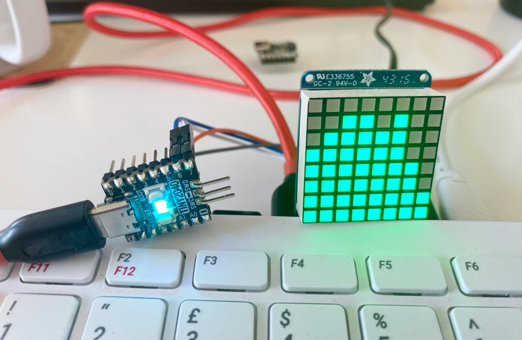
RP2040 I2C Host Firmware
Caution
This code has been superseded by Depot.
This page details the firmware which runs on RP2040-based I²C host devices. When running, the firmware listens to the UART hosted by the RP2040’s USB connection for the following commands and for read/write indicators.
The current version is 1.1.3. Read the release notes.
Caution
I strongly recommend you build the firmware with Pico SDK 1.5.0 or above.
Processing Incoming Data
The first received byte is checked by the firmware. If the value is less than 0x80,
the code checks for a command, otherwise it processes the bytes as
a read or write operation.
Commands
Command |
Arguments |
Description |
|---|---|---|
|
Set the bus-host’s current mode |
|
|
Get bus-host device info |
|
|
|
Set the bus-host’s LED state1 |
|
||
|
Get last device error. Returns an error code byte |
Command |
Arguments |
Description |
|---|---|---|
|
|
Configure the I²C bus. This must be performed before the bus is |
|
Set I²C bus frequency to 100kHz |
|
|
Set I²C bus frequency to 400kHz |
|
|
Initialise the I²C bus for use |
|
|
Reset the I²C bus |
|
|
Manually issue an I²C |
|
|
|
Start an I²C read or write operation targeting a specific device |
|
Scan the I²C bus for devices. If the bus is not initialised when this |
1 If SHOW_HEARTBEAT is not defined in CmakeLists.txt, this call will respond with an ERR signal.
2 Bits 7 through 1 are the target device’s I²C address. Bit 0 is the operation required: 1 for read, 0 for write.
3 Bit 7 is the pin state: 1 for logic high, 0 for logic low. This is ignored in read operations.
Bit 6 is the pin direction: 1 for an output, 0 for an input. Bit 5 is the operation required: 1 for read, 0 for write.
Bits 4 through 8 are the target pin number (0-31).
Commands are acknowledged with an ACK (0x0F) or an ERR (0xF0). Note that these values may change.
Commands that return arbitrary amounts of data append the data with \r\n as an end-of-sequence marker.
Read and Write I²C Operations
The outcome depends on the value of the first byte in the sequence.
If the value is in the range 0x80 to 0xBF, it is a read operation and the number of bytes to read is given by: value - 0x80 + 1.
If the value is in the range 0xC0 to 0xFF, it is a write operation and the number of bytes to write is given by: value - 0xC0 + 1.
These bytes follow the state byte.
Only 64 bytes can be requested/written at a time. This is usually sufficient, but for larger amounts, issue subsequent requests for 64 bytes or less.
Device Scan Format
Requesting a device scan returns is a string of I2C addresses separated by full-stops. Each address is a 7-bit value encoded as two-digit hex numbers.
If no devices are present, Z\r\n is returned.
Host Information Format
Requesting host information returns a sequence of integers and strings separated by full stops and followed by \r\n.
Value |
Size |
Notes |
|---|---|---|
Is I2C ready? |
2 |
Binary value: |
Is I2C being used? |
2 |
Binary value: |
I2C bus ID |
2 |
|
I2C SDA pin |
2-3 |
0-31 in decimal form |
I2C SCL pin |
2-3 |
0-31 in decimal form |
I2C bus frequency |
2 |
|
I2C address |
2-4 |
8-127 in decimal form |
Firmware version |
6-12 |
Major, minor and patch values as separate fields |
Firmware build |
2-4 |
1-999 |
Unique RP20240 ID |
17 |
16-byte value as two-digit hex values |
Board type |
2-17 |
Per board ID string, eg. |
Note Size includes the post-value separator.
Error Codes
Errors are defined in the file errors.h.
The format is as follows:
Bits 6-8 — The mode.
Bits 1-5 — A mode-specific error code.
Mode |
Mode Bits |
|---|---|
General |
|
I2C |
|
SPI |
|
UART |
|
1-Wire |
|
GPIO |
|
Reserved |
|
Source code
The I²C Host firmware source code can be found in this GitHub repo.
Build and Deploy the I²C Host Firmware
Note
The following assumes you have the Pico SDK installed on your build machine and that the PICO_SDK_PATH environment variable is set.
Clone the repo.
Navigate to the repo directory.
Run
cmake -S . -B firmwarebuild.Run
cmake --build firmwarebuild.Write the firmware depending on which board you are using:
./deploy.sh /path/to/device firmwarebuild/firmware/pico/firmware_pico_rp2040.uf2./deploy.sh /path/to/device firmwarebuild/firmware/qtpy/firmware_qtpy_rp2040.uf2./deploy.sh /path/to/device firmwarebuild/firmware/promicro/firmware_promicro.uf2./deploy.sh /path/to/device firmwarebuild/firmware/tiny/firmware_tiny2040.uf2./deploy.sh /path/to/device firmwarebuild/firmware/trinkey/firmware_trinkey2040.uf2
The deploy script tricks the RP2040-based board into booting into disk mode, then copies over the newly build firmware. When the copy completes, the RP2040 automatically reboots. This saves of a lot of tedious power-cycling with the BOOT button held down.